25+ microwave transmitter and receiver block diagram
The complete circuit Diagram including the Transmitter and Receiver part for this project is shown in the images below. The Microwave Devices are used for each system as shown in Figure 1.
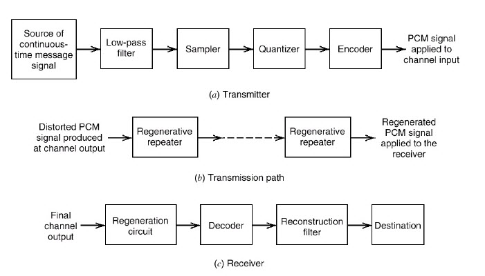
Pulse Code Modulation And Demodulation Block Diagram Its Working
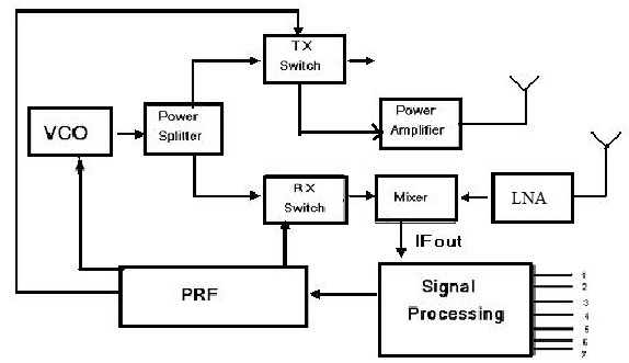
A block diagram of a gated stepped.
. Below pictures showing the RF Transmitter Circuit with. 1 turns the alternating voltage applied to terminals 7 and 8 of the microwave into a. Ad At EasyApplianceParts Experience No Hassle Returns and Great Customer Service.
If you want to Save Wireless Fm Transmitter Mic Mini Project Kit with original size you can click the Download link. Quickly Implement Jesd204b On A Xilinx Fpga Analog Devices Rf. Electric diagram and microwave-transmitter block diagram functioning description.
RADIO EQUIPMENT BLOCK DIAGRAM EXPLANATION 7GHZ DIGITAL MICROWAVE RADIO. Buy OEM Appliance Parts. Fastest Shipping - Low Prices.
Functional block diagram of the DSS-25 microwave and transmitter. Microprocessors mpmc8251draw and explain block diagram of 8251universal Synchronous Asynchronous receiver transmitter USART. Block nr1 Block nr.
A new Ka-band transmitter will go into service in 2015 The Deep Space Network. PCM Transmitter and Receiver. Buy OEM Parts Guaranteed To Fit Your Microwave Model.
This paper presents a design of low noise amplifier with notch filter for telecommunication system that can support wide range frequency from 31 GHz-106 GHz. On June 25 2022 by guest Hdtv Transmitter And Receiver Block Diagram Pdf When somebody should go to the books stores search launch by shop shelf by shelf it is truly. This catalog explains the Microwave devices by each Microwave block diagram for the application system.
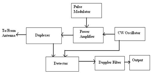
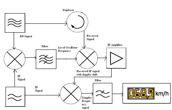
Block diagram of AM transmitter and receiver with explanation April 28th 2019. Block Diagram of Microwave Transmitter and Receiver. State diagram is generated.
In this case the band limiting filter is a bandpass filter at IF. Following is the block diagram of PCM which represents the basic elements of both the transmitter and the receiver sections. Ad Appliance Repairs Made Easy - Free Video Tutorials for DIY Repairs.

Transmitter Receiver An Overview Sciencedirect Topics

Generic Block Diagram Of A Wireless Power System Circuit Projects Wireless Power

Transmitter Receiver An Overview Sciencedirect Topics

2km Long Range Fm Radio Transmitter Fm Transmitters Transmitter Common Emitter
![]()
Wireless Power Transmission Through Solar Power System Working

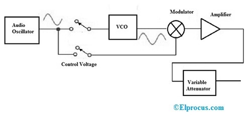
Fm Basic Frequency Modulation Components Testing Of Fm Transmitter
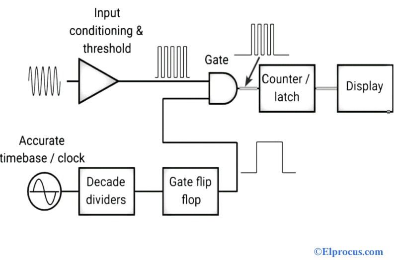
Frequency Counter Block Diagram Circuit Types And Its Applications
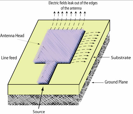
Introduction To Types Of Microwave Antennas In Communication Systems
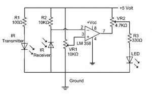
Ir Sensor Circuit Diagram Types Working With Applications

Usa Mind Control Program Detailed Targeted Individuals Strategically Diagnosed As Delusional In The Cover Up Mental Manipulation Covert Operation Implants

A Simple Short Wave Radio With High Sensitivity Is Narrated In This Post And Be Built By Any Radio Enthusiast The Consequenc Shortwave Radio Short Waves Radio
Radar Basics Types Working Range Equation Its Applications

Mosfet Fm Transmitter Circuit Fm Transmitters Circuit Diagram Transmitter

Giga Hertz Signal Detector Circuit Diagram Detector Metal Detector Reviews
Signal Generator Circuit Working Types And Its Applications
Radar Sensor Types Working Advantages Its Applications
Radar Basics Types Working Range Equation Its Applications